Posts

Showing posts from April, 2017

Microprocessor,Microcomputer,Microprocessor Characteristics and Features of Microprocessor

Introduction To Microprocessor Microprocessor:- A microprocessor is a central processing unit build on a single IC. It consists of very small transistors fabricated on a single semiconductor IC. One or more microprocessors typically serve as a CPU in a computer system. Microcomputer:- •Microcomputer is a digital computer in which there is one microprocessor which acts as a  CPU. •Examples: A desktop computer, palmtop, notebook, laptop, etc. Characteristics of Microprocessor:- • INSTRUCTION SET: •The set of instructions that a microprocessor can understand. • BANDWIDTH: •The number of bits processed in a single instruction. •CLOCK SPEED: The number of operations performed by the processor per second. •Width of data bus: •It defines the number of bits that can be transferred through data bus. •Width of Address Bus: •This parameter decides the memory addressing capability of the microprocessor. • Interrupt Capability: • This feature int

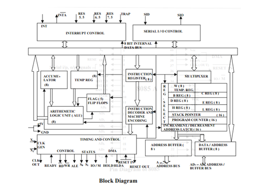
Architecture of Microprocessor 8085

Image
Architecture of Microprocessor 8085 Pins of 8085 Microprocessor are:- Address bus A15-A8, it carries the most significant 8-bits of memory/IO address. Data bus AD7-AD0, it carries the least significant 8-bit address and data bus. Control and status signals These signals are used to identify the nature of operation. There are 3 control signal and 3 status signals. Three control signals are RD, WR & ALE. RD  − This signal indicates that the selected IO or memory device is to be read and is ready for accepting data available on the data bus. WR  − This signal indicates that the data on the data bus is to be written into a selected memory or IO location. ALE  − It is a positive going pulse generated when a new operation is started by the microprocessor. When the pulse goes high, it indicates address. When the pulse goes down it indicates data. Three status signals are IO/M, S0 & S1. IO/M This signal is used to differentiate between IO and Mem

Addressing Modes of 8085

       Addressing Modes of 8085      • The method by which the address of source of data or the address of destination of result is given in the instruction is called Addressing Modes.     •The term addressing mode refers to the way in which the operand of the instruction is specified in the instruction.      Types of Addressing Modes 8085 Microprocessors • Intel 8085 uses the following addressing modes: • Direct Addressing mode • Register Addressing Mode • Register Indirect Addressing Mode • Immediate Addressing Mode • Implicit Addressing Mode Direct Addressing Mode • In this mode, the address of the operand is given in the instruction itself . • Example: LDA 2500H • This instruction loads the contents of memory location 2500H in accumulator. • LDA is the operation. • 2500H is the address of the source. • Accumulator is the destination. Register Addressing Mode • In this mode, the operand is in general purpose register . • Example: M

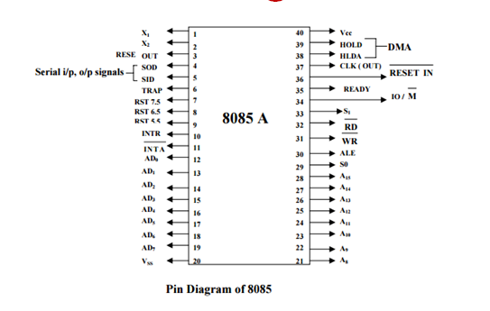
8085 Microprocessor

Image
8085 Microprocessor 8 bit microprocessor Introduced by INTEL in 1977 Use NMOS technology The “5” in the model number came from the fact that the 8085 requires only +5V power supply rather than +5V, -5V and +12V as required by 8080 microprocessors. It can work up to 5 MHz frequency. It has 40 pins. Address Bus : 16 bits Can address up to 2 16 = 65536 bytes ( upto 64 Kbytes) AD0-AD15 Data bus : 8 bits (D0-D7) Program Counter: 16 bits Stack pointer (SP): 16 bits Six 8- bit general purpose registers arranged in pairs: BC, DE and HL. Flag Register      • D4: Auxiliary carry flag • This flag is set to whenever a carry is transferred from D3 to D4, i.e. from lower nibble to higher nibble. • D2: Parity flag • This flag is set to 1 when the result consists of even number of ones. • D1: Carry Flag • This flag is set to 1 when the arithmetic and logical operation results in a carry.  Interrupts in 8085 Microprocessor • The processor